Physical Address
304 North Cardinal St.
Dorchester Center, MA 02124
Physical Address
304 North Cardinal St.
Dorchester Center, MA 02124

A primitive statement can either be true or false, in much the same way a light switch can either be on or off. Expanding on this analogy, we can connect primitive statements into larger compound statements using logical connectives in much the same way that multiple light switches can be connected in an electrical circuit to a light bulb. An assignment of truth values to each primitive statement that makes the compound statement true is thus related to a configuration of light switches that allows electricity to flow through a circuit to turn on a light bulb.
These electrical circuits can be designed to be as complicated or as simple as we desire, but no matter how complicated an electrical circuit can be, we can use the laws of logic to simplify circuits, making them easier to construct.
A switching network is a collection of switches and wires connecting two terminals. For our purposes, one terminal will be a power source (a battery, electrical outlet, or some other power source) and the other terminal will be a light bulb.
The goal is to manipulate the switches in such a way that electricity can flow from the power generating terminal to the light bulb, thus activating the light bulb (getting the light bulb to emit light.)
In these switching networks, each switch present is either open (0), meaning it does not let electricity flow through, or it is closed (1), meaning it does allow electricity to flow through.
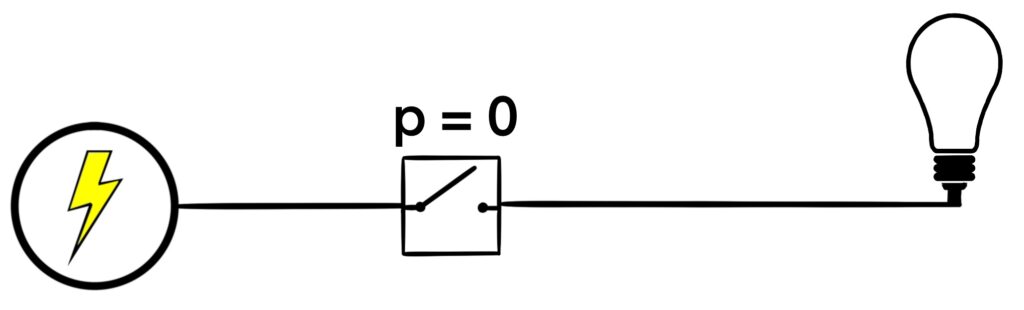
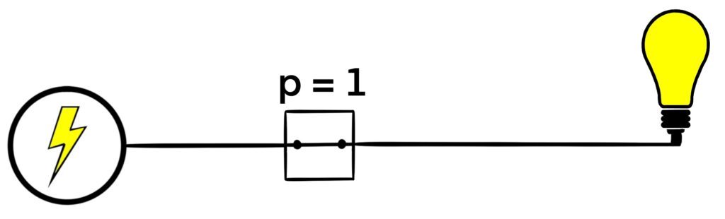
Figure 1.5.1: Here, we see a switching network with a single switch, labeled p. In (a), we see that an open switch corresponds to a value of 0 for the switch label. In this case, the light bulb is not shining. In (b), we see that a closed switch corresponds with a value of 1 for the switch label. Here, the light bulb is shining.
As a short-hand for describing these kinds of networks, we’ll simply place the switch’s label within the box used for the switch in the network.
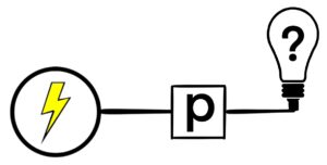
Figure 1.5.2: Here is a network with a single switch. If p = 0, then the light bulb does not turn on. If p = 1, the light bulb turns on.
For these switches, whether the light bulb is on or off depends on the value of the label. If p = 0, then the light bulb does not shine. If p = 1, then the light bulb does shine.
We can of course include more than one switch in a single switching network. In particular, things get interesting when two switches are included.
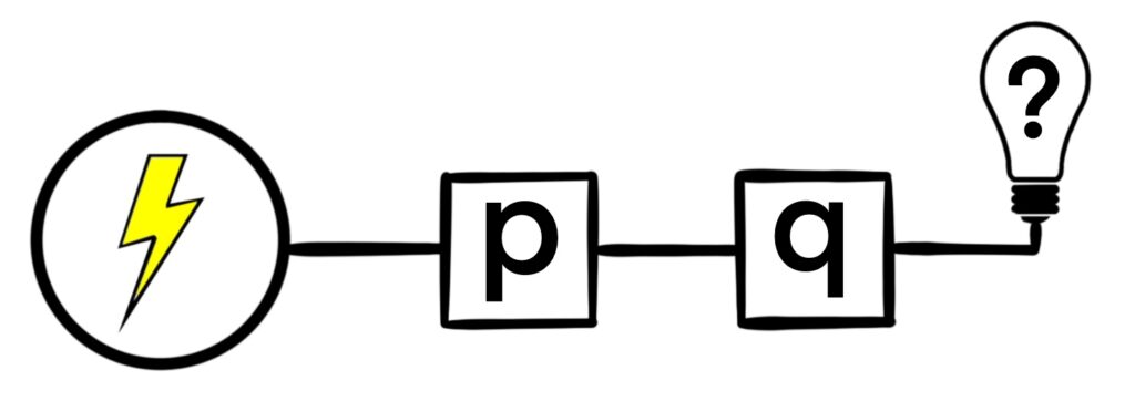
Figure 1.5.3: When switches are placed along the circuit in sequence, then both switches must be closed for the light to shine (both labels would have to be equal to 1.)
One way to include a second switch is to simply place it further along the circuit than the first switch. In this case, both switches must be closed (the associated labels must be equal to 1) in order for the light bulb to shine. If any switch is open, then the light does not shine.
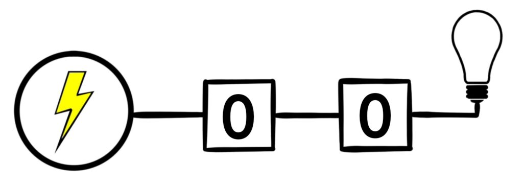
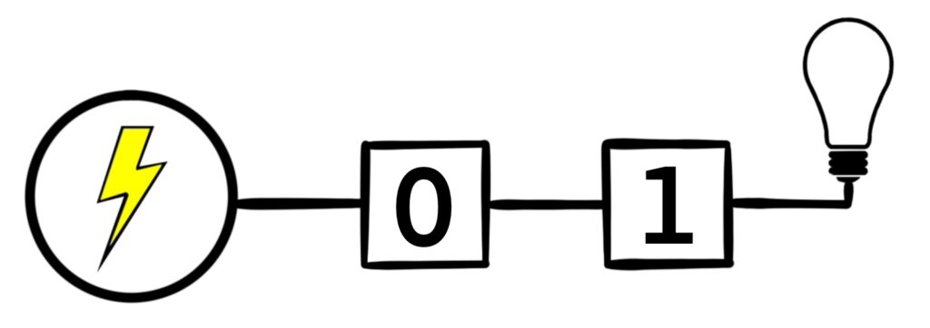
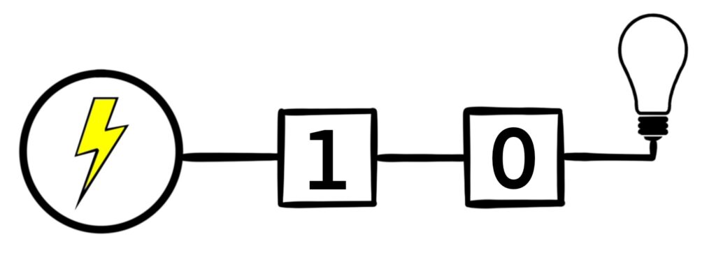
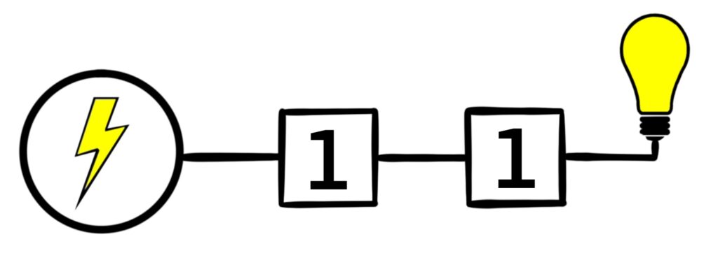
Figure 1.5.4: There are four possible configurations for this kind of switching network. In (a), both switches are open, and so electricity does not flow to the light bulb. In (b) and (c), one of the switches is open, but electricity still can’t flow to the light bulb. Only in (d) does electricity reach the bulb because both switches are closed.
The switches in Figure 1.5.3 are said to be connected in series. When switches are connected in series, they must all be closed in order to allow electricity flow through the entire circuit.
Notice that when two switches are connected in series, the light bulb is on when
p ∧ q = 1.
When p ∧ q = 0, the light does not shine. This is the connection between switching networks, and propositional logic.
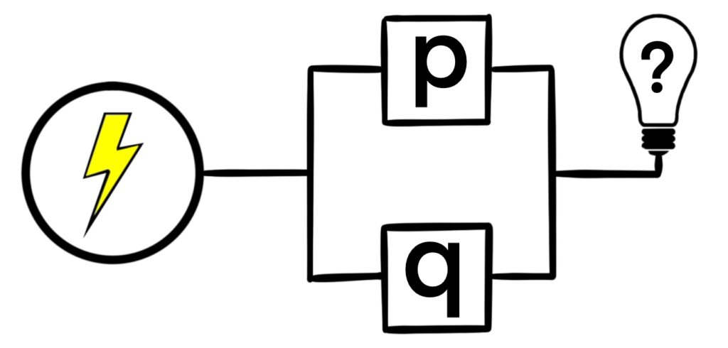
Figure 1.5.5: Here, we essentially create a branching path. If at least one switch is closed, then the light bulb emits light. In other words, if switch p or switch p is closed, the light bulb shines.
Another way to connect two switches is as a branching path in the network as seen in Figure 1.5.5. Here, as long as at least one of the switches is closed, the light bulb turns on.
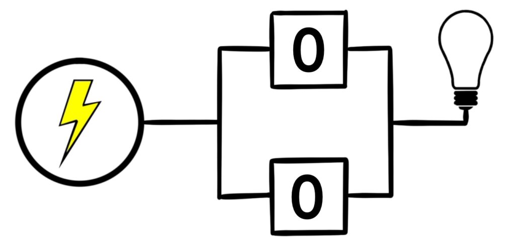
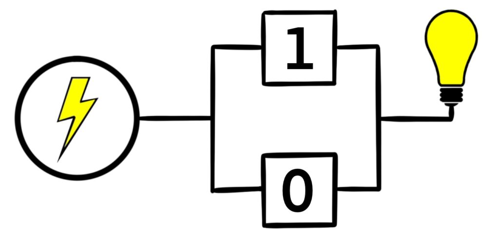
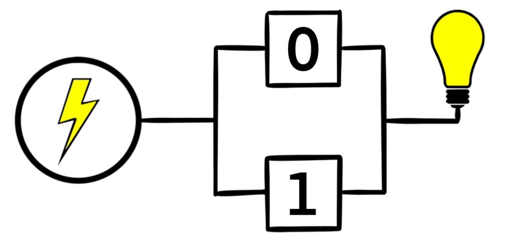
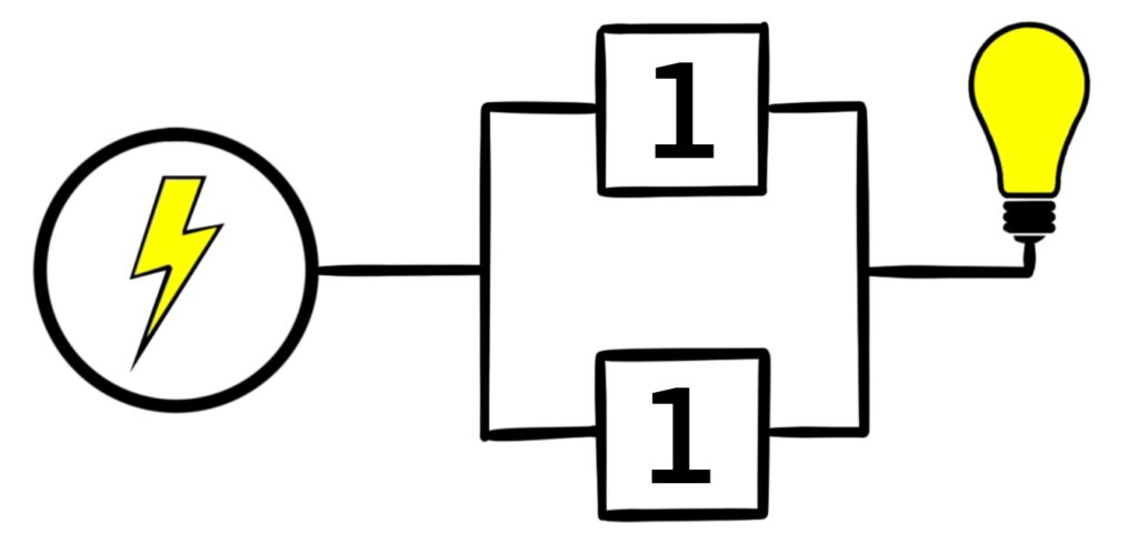
Figure 1.5.6: Just like with Figure 1.5.4, there are four possible configurations the circuit can exist in. When both switches are open, the light bulb is off. Otherwise, the light bulb shines.
The switches in Figure 1.5.5 are said to be connected in parallel. In this case, when at least one of the switches is closed, the light bulb shines. When switches are connected in parallel like this, the light bulb is on when
p ∨ q = 1.
Again, the light does not shine when p ∨ q = 0.
We can design circuits using a multitude of switches that are connected in series and in parallel. As we concoct ever more complex switching networks, keep in mind that these networks correspond to some logical expression, and when that logical expression evaluates to true, the light bulb shines.
Consider the following switching network.
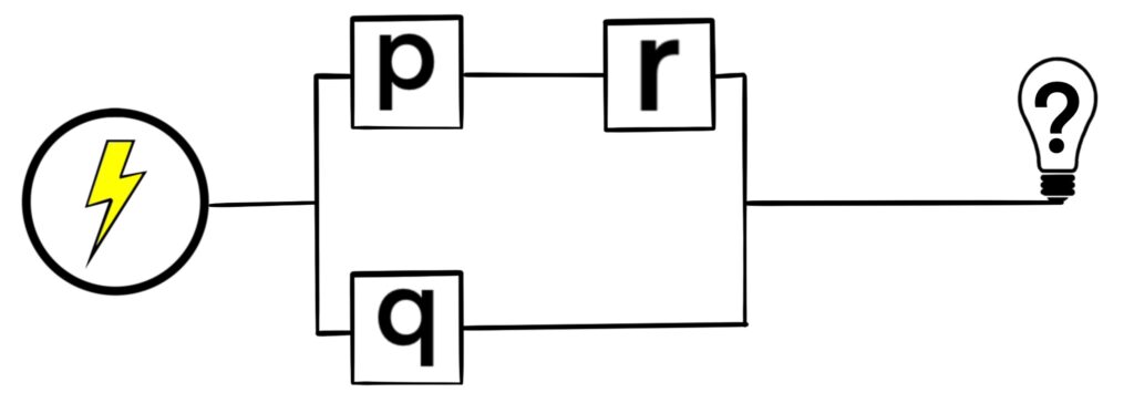
Surely we can model this circuit using a logical expression as we did with both the series circuit and the parallel circuit described above.
First, we notice that there are 3 switches in total: p, q, and r. This means our logical expression will use those letters.
Next, we notice that the circuit starts of with a branch, meaning we have a parallel circuit: one branch uses letters p and r, while the other branch uses the switch labeled q. So our logical expression will look something like this:
(something with p and r) ∨ q.
To determine how the p and r switches are related, notice that those switches are connected in series, meaning the logical expression dealing with p and r is simply p ∧ r. This gives us our final logical expression as
(p ∧ r) ∨ q.
So, the light bulb will shine when (p ∧ r) ∨ q = 1. Here is the associated truth table.
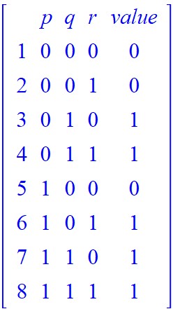
There are a couple of ways to turn the light bulb on. We can close switches q and r, while opening switch p. Alternatively, we could close switches p and r, while leaving switch q open.
Our next example will involve many more switches, some of which will be inverted (that is to say, we use the negation of the labels on some switches.)
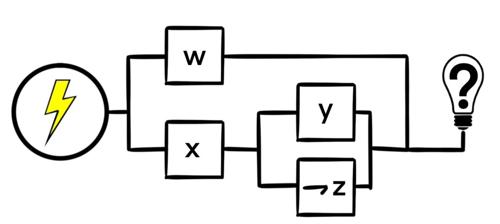
Consider the following monster switching network.
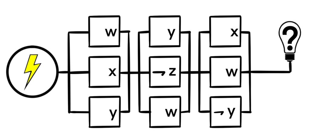
In this network, we have 4 total labels: w, x, y, and z. Some are repeated, and some are negated, so we’re dealing with quite a complicated network, but just as before, we can break this switch down into a bunch of series circuits and parallel circuits.
It looks like the entire network is 3 groups of switches connected in series, those 3 groups being (w, x, y), (y, ¬z, w), and (x, w, ¬y), so initially, the logical expression associated with this switching network looks like
(w, x, y) ∧ (y, ¬z, w) ∧ (x, w, ¬y).
Each of the 3 groups of switches are connected in parallel, giving us (w ∨ x ∨ y), (y ∨ ¬z ∨ w), and (x ∨ w ∨ ¬y). This means our final logical expression is
(w ∨ x ∨ y) ∧ (y ∨ ¬z ∨ w) ∧ (x ∨ w ∨ ¬y).
Whenever that expression equals 1, the light bulb will turn on. One such configuration is given by
w = 1, x = 0, y = 1, z = 0.
Since we model switching networks using logical expressions, it seems reasonable that simplifying the associated logical expression will yield a smaller switching network that behaves identically to the given switching network. That is to say that once we simplify a switching network, the light bulb in each network will be on given the same input values, and will be off on the same input values.
Can we simplify the circuit from Example 1.5.2? Let’s try and use the laws of logic to do so.
| (w ∨ x ∨ y) ∧ (y ∨ ¬z ∨ w) ∧ (x ∨ w ∨ ¬y) | Law of Logic Used | |
| ⟺ | (w ∨ x ∨ y) ∧ (y ∨ ¬z ∨ w) ∧ (w ∨ x ∨ ¬y) | Commutative Law of ∨ |
| ⟺ | (w ∨ x ∨ y) ∧ (w ∨ y ∨ ¬z) ∧ (w ∨ x ∨ ¬y) | Commutative Law of ∨ |
| ⟺ | (w ∨ x ∨ y) ∧ (w ∨ x ∨ ¬y) ∧ (w ∨ y ∨ ¬z) | Commutative Law of ∧ |
| ⟺ | [(w ∨ x) ∨ y] ∧ (w ∨ x ∨ ¬y) ∧ (w ∨ y ∨ ¬z) | Associative Law of ∨ |
| ⟺ | [(w ∨ x) ∨ y] ∧ [(w ∨ x ∨) ¬y] ∧ (w ∨ y ∨ ¬z) | Associative Law of ∨ |
| ⟺ | [(w ∨ x) ∨ (y ∧ ¬y)] ∧ (w ∨ y ∨ ¬z) | Distributive Law of ∨ over ∧ |
| ⟺ | [(w ∨ x) ∨ F0] ∧ (w ∨ y ∨ ¬z) | Inverse Law |
| ⟺ | (w ∨ x) ∧ (w ∨ y ∨ ¬z) | Identity Law |
| ⟺ | (w ∨ x) ∧ [w ∨ (y ∨ ¬z)] | Associative Law of ∨ |
| ⟺ | w ∨ [x ∧ (y ∨ ¬z)] | Distributive Law of ∨ over ∧ |
At this point, none of the other laws of logic look like they can be used, so our final logical expression is
w ∨ [x ∧ (y ∨ ¬z)].
It looks like the switch w is connected in parallel to [x ∧ (y ∨ ¬z)]. Digging deeper into the circuit, it looks like switch x is connected in series with (y ∨ ¬z). Finally, it looks like y and ¬z are connected in parallel.
Here is our simplified circuit:
This circuit looks much simpler! There are 5 fewer switches than before, and no label is repeated. Furthermore, because we used the laws of logic, we know that this circuit behaves in the exact same way as the circuit presented in Example 1.5.2. One assignment of truth values to w, x, y, and z will either keep the bulb off in both circuits, or turn the light bulb on in both circuits.
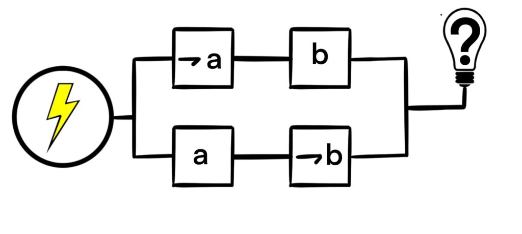
Notice that we only talked about two circuit constructs: series circuits (∧) and parallel circuits (∨). What about the exclusive-or (⊻) circuit? There is no associated circuit construct for the exclusive-or operation, so we would need to make such a circuit using series circuits and parallel circuits.
To do this, we can come up with a logical expression using only ¬, ∧, and ∨ that is logically equivalent to ⊻. Here, we’ll use switch labels a and b. For a ⊻ b, we need to have ¬a ∧ b, or we need to have a ∧ ¬b to achieve the desired effect. As such, we have that
a ⊻ b ⟺ (¬a ∧ b) ∨ (a ∧ ¬b).
This expression yields the following circuit:
There are also circuits for the → and ↔ operations as well, but they also rely on the ∧ and ∨ operators.